Dissolved Air Flottation(DAF)
Introduction:-
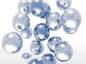
DAF is a fast and highly efficient method for removing turbidity, color, suspended
solids and other contaminants from water using air bubbles. These specially created
air bubbles are first mixed with wastewater, attach themselves to solids
present and then separate them by flotation leaving clarified water behind. DAF
has become widely accepted for use in potable water treatment, municipal wastewater
as well as a variety of industrial applications
Working Principle:-
Dissolved Air Flotation (DAF) is an efficient flotation method
for water clarification.
Dissolved Air Flotation (DAF) is a process for the removal of fine suspended material
from an aqueous suspension. The term "flotation" indicates something floated on
or at the surface of a liquid.
The DAF provides the energy for effective flotation in the form of extremely fine
air bubbles, which become attached to the suspended material to be removed. This
attachment of bubbles to the particle "reduces" the density of the particle resulting
in increased buoyancy, thus effecting flotation. Chemical conditioning is often
used to increase the effectiveness of the dissolved air flotation process.
The most reliable and positive method of producing bubbles of the proper size is
to dissolve air into water under pressure and to then reduce the pressure of the
solution. As the pressure is reduced, the air comes out of solution in the form
of micro bubbles.
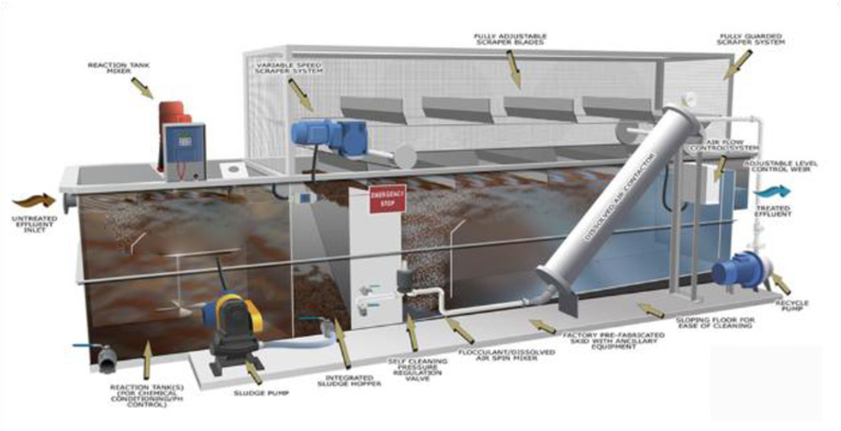
- Wastewater is pretreated with chemicals.
- Treated influent is fed to DAF unit.
- Recycle is drawn off effluent line and is sent through the air dissolving system
and then sent back into the DAF.
- Air is released from the recycle flow and the bubbles help to float solids in the
DAF tank.
- Float is skimmed from the top of the tank.
- Clear effluent flows out of the unit.
Applications:-
Dissolved air flotation is best applied to remove materials that normally settle
slowly, persist by remaining in suspension, or have a tendency to float.
- Aircraft Maintenance
- Algae Removal
- Automotive Industry
- Bakery Waste
- Ballast Water
- Canning
- Chemical Processing Plants
- Fiber Recovery
- Heavy Metal Recovery
- Latex
- Meat Packing
- Paint Waste
- Pet Foods
- Pharmaceutical
- Potato Processing
- Poultry Processing
- Prepared Foods
- Pulp and Paper Mills
- Refineries
- Rendering
- Seafood Processing
- Slaughter House
- Tank and Truck Cleaning
- Tanning
- Textiles
- Vegetable Oil
Advantages:-
- Initial construction costs are reduced 30-50%
as compact DAF clarifiers are less costly to construct and install than larger settling
basins.
- Further savings are achieved when the plant is
enclosed in a building as less area is required for DAF.
- Chemical costs are reduced as flotation in general
requires less chemical pretreatment to form a light, small floc.
- DAF is ideal for treatment plants in remote locations
or with limited available area.
- Continuous operation
- Application versatility
- Ease of operation, requires minimal attention
- Simple, durable design for low maintenance and
long life
Tube Settler:-
Introduction:-
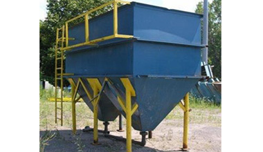
TUBE SETTLER is the most effective and alternative to the conventional sedimentation
process. And, unlike the sedimentation process that demands a great deal of today's
valuable space, the compact TUBE SETTLER is not marely a great space saver but helps
cut down civil engineering costs substantially.
Basic Structure:-
Multiple tubular Channels-inclined at an angle and adjacent to each other-separate
the suspended solids from water or any other liquid effluent.
Individual tubes are continuous and smooth to minimise mixing of currents within
the tube. The configuration and shape of each tube is design to obtain a low Reynolds
number and laminar flow conditions for rapid accumulation and settlement of solids
through the tubes. The high surface area of tubes enabling substantial improvement
of settling capacity
Working Principle:-
This is a COMBINED UNIT consisting of FLASH MIXER/FLOCCULATOR and SETTLING TANK.
FLASH MIXER TANK:-
The tank will be fitted with a mechanism consisting of :-
TEFC squirrel cage induction IP55 motor
- Worm gear box.
- Turbine type impeller.
- Shaft.
- Rigid coupling connecting gear box to agitator
shaft.
- Base plate with coupling.
- Support channels or beams across the tank shall
be supplied and laid by client.
FLOCCULATOR TANK:-
The tank will be fitted with a Mechanism consisting of :-
- Support plate.
- Flocculator drive with motor and gear box.
- Rigid coupling.
- Central shaft.
- Flocculation paddles.
SETTLING TANK (in steel):-
The unit shall be made of MS plates and the shell will have suitable supports with
inlet, outlet and drain arrangement. It will have steel launder and collection pipes.
Settling will be efficiently achieved by tubes which shall be special PVC units
with high settling efficiency. The tubes shall be installed and fitted to make continuous
settling area and shall be supported on steel supports.
A common walkway with handrails shall be provided to cover Tube Settler and Flocculator/Flash
Mixer.
The tank shall be painted with Epoxy Primer and Epoxy Paint from inside and Red
oxide Primer and Synthetic Enamel Paint from outside.
Applications:-
- Raw water classification
- Waste water treatment
- Ash/Scrubber waste management
- Brine classification
- Coal and other mineral separation
- Food and Dairy processing and waste treatment
- Iron Removal
- Millscale Separation
- Pulp and Paper
- Distillery waste treatment.
- Pretreatment to RO unit
Advantages:-
- The advantages of tube settlers can be applied
to new or existing clarifiers/basins of any size:
- Clarifiers/basins equipped with tube settlers
can operate at 2 to 4 times the normal rate of clarifiers/basins without tube settlers.
- It is possible to cut coagulant dosage by up to
half while maintaining a lower influent turbidity to the treatment plant filters.
- Less filter backwashing equates to significant
operating cost savings for both water and electricity.
- New installations using tube settlers can be designed
smaller because of increased flow capability.
- Flow of existing water treatment plants can be
increased through the addition of tube settlers.
- Tube settlers increase allowable flow capacity
by expanding settling capacity and increasing the solids removal rate in settling
tanks.
- Very cost economical since it uses 1/10th of space
required by conventional clarifiers.
- No moving parts, operates totally on Gravity.
- No maintenance list.
- Laminar flow ensures excellent treated water quality.
- Wide choice of materials of construction such
as steel, concrete/FRP.
- Non-corrosive tubes can be lifted easily for cleaning
without shutdown.
- Flexible configurations
- Required Very Less Space
- Easy installation
- No Power Consumption
- Simple in Operation
- Easily Mobility
Rapid Mixer / High Speed Agitator:
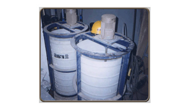
Introduction:-
Lichens Flash mixers are specially designed and fabricated for
the process requirement of water and wastewater treatment. The mixer design ensures
efficient, minimum energy consumption and long life. This equipment blends coagulants
and other chemicals with water / wastewater prior to flocculation. The aggressive
agitation results in instantaneous and effective mixing of chemicals. This unit
is also useful for general mixing.
Specification :-
This unit is suitable for installation in concrete/HDPE tank.
Each unit will consist of :-
- TEFC squirrel cage induction motor with IP55 degree
of protection.
- Stainless steel shaft.
- Stainless steel propeller.
- Interconnecting coupling.
- Clamp.
IMPELLER Four blades pitched paddle type impeller.
Support channels and beams shall be supplied and laid by client.
- Suitable for intermittent & continuous processes.
- Compact design & economically priced.
- Modular design enables various mounting arrangements.
(i.e. from open tank to closed tank.)
- High efficiency impellers designed for specific
process applications.
- Variable output speed by Variable Frequency Drive.
- Oversized tapered roller bearings for long life
continuous processes.
- Power range from 0.06 HP to 25 HP & onwards.
Applications:-
- Re-suspending settled solids before pumping out
like solvents, paints.
- Fluid batch preparation before injecting into
the process.
- Preventing stratification of fluids-coatings,
lubricants.
- Heat transfer.
- PH control
- High viscosity mixing.
- Bringing various fluids to a uniform blend like
dyes.
- Gas dispersion
Floculator:-
Introduction:-
Flocculation is the agglomeration of destabilized particles into microfloc and after
into bulky floccules which can be settled which are popularly called as floc. The
addition of another reagent called flocculant or a flocculant aid may promote the
formation of the floc.
Working Principle:-
Lichens Flocculator provides gentle agitation by slow moving paddles. This action
serve to break up the mass rotation of liquid and promote mixing. The specially
designed flocculating paddles enhance flocculation of the feed solids. Agglomeration
of the destabilised colloids is achieved as a result of particulate transport in
the flocculation compartment. Increased particle contact will promote floc growth
and aids faster settling.
Specification:-
The unit will consist of:
- Support plate.
- Flocculator drive with motor and gear box.
- Central shaft
- TEFC squirrel cage induction IP55 motor.
- Worm gear box.
- Turbine type impeller.
- Rigid coupling connecting gear box to agitator
shaft.
- Base plate with coupling.
- Support channels or beams across the tank shall
be supplied and laid.
SALIENT FEATURES OF “Lichens” LOW SPEED AGITATOR
- Sturdy Drive arrangement with a heavy base plate.
- A heavy duty bearing housing to take care of axial/radial
loads, bending moments and thrust loads.
- Solid shaft adequately designed to resist bending
moment.
- Impeller designed for maximum turbulence and efficiency.
Advantages:-
Flocculator mainly find application in the following areas:
- Municipal water treatment plants
- Municipal wastewater treatment plants
- Industrial water and wastewater treatment plants
Clarifier:-
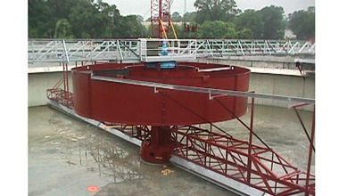
Introduction:-
Clarifiers separate solids from the liquid stream. In water & wastewater treatment
the terms clarifier and sedimentation tank are synonymous.
Working Principle:-
Lichens Clarifiers are extensively used for continuous mechanical removal of settleable
solids from wastes. These can be either Bridge or Centre column supported. In a
centre feed design the wastewater is carried to the centre of the tank, the wastewater
enters a circular well designed to distribute the flow equally in all directions.
The sludge removal mechanism revolves slowly and may have two or four arms equipped
with scrapers.
The drive unit can be central or peripheral and also manufactured with half/full
scrapping arm. They can also be equipped with scum removal system. Besides conventional
clarifiers, high rate clarifiers with parallel plate separators and tube settlers
are also offered.
Type of Clarifiers:-
The two types of clarifiers are:
Central Drive Clarifier:
Basic Structure:
Full diameter bridge supports the central drive mechanism. The scraper frames are
fitted to the drive shaft which is connected to the central gear. A bearing housing
at the bottom serves as a guide to the drive shaft. The scrapers are fitted to the
scraper frames. The influent well is suspended from the bridge.
CENTRALLY DRIVEN CLARIFIERS 4 MT. DIA TO 50 MT. DIA
This unit is suitable for installation in client’s concrete tank. Each unit will
consist of :-
- Fixed full bridge with walkway and handrail from
one end to centre.
- Influent (feed) well.
- Drive arrangement consisting of motor, gear box,
pulleys, V- belts, base plate.
- Heavy duty bearing housing to take care of undulations,
torque and loads.
- Central shaft.
- Rake arms with blades and tie rods.
- Rake blades in sludge hopper.
All pipes, including inlet, outlet and sludge pipes are excluded from our scope.
Peripheral Drive Clarifier :
Basic Structure:
The bridge is pivoted on a cast steel bearing at the centre on the centre pier and
at the periphery it rests on wheel carriage fitted with wheels and drive unit. Garlon,
C.I. polyurethane lined or cast steel wheels are supplied. Rails are provided for
cast steel wheels.
The scrapers are suspended from the bridge. Slip ring unit is mounted on the central
bearing.
PERIPHERALLY DRIVEN CLARIFIERS 4 MT. DIA TO 50 MT. DIA
This unit is suitable for installation in client’s concrete tank.
Each unit consists of :-
Rotating half bridge with walkway and handrails. - End Drive with motor, gear box,
base plate, V-belts. - Central bearing housing and slip ring assembly. - Wheels
rubberized C.I. - Central cage. - Clarifier rake arms with blades. All pipes, including
inlet, outlet and sludge pipes are excluded from our scope.
Lichens Clarifiers have unique design of additional scrapper blades in the hopper.
This prevents any possible clogging and thus prevents costly shutdowns.
IN CLARIFIER FOLLOWING ITEMS ARE OPTIONAL :-
- V-notch weir plate.
- Skimmer blade.
- Scum baffle.
- Scum box.
- Telescopic arrangement (excluding piping and valves
in an around sludge pit).
|
COMPARISON
OF CLARIFIER
|
|
DESIGN
OF Lichens
|
DESIGN OF OTHERS
|
|
Based on Simon Hartley, U. K., who are operating since, 1902. British are highly
conservative and their designs are heavy and safe.
|
Technology basis does not exist.
|
|
|
|
|
BRIDGE :- Scientifically designed by senior and experienced Structural
Engineers, using heavy sections. This takes care of working loads along with drive
arrangement to make its life long. The railing on the bridge is not only heavy but
also safe.
|
At some places, the bridge has sagged and even fallen.
|
|
|
|
|
SCRAPPER BLADES :- The scraper blades system shall consist of single-blade
lengths arranged to overlap in series, producing an effect equal to a continuous
spiral blade (volute formation arrangement). Each blade length is fitted with an
easily renewable rubber strip. The blades shall ride along the contours of the tank
floor and automatically adjust to any slight undulation. Thus, the scrappers are
designed in such a way that entire floor area is covered. This ensures, high sludge
removal efficiency from all points and also results in better overflow clarity.
Twin scrapper arms will scrap twice in 1 revolution, achieving High Sludge removal
Efficiency.
|
The blade formation does not result in to uniform and continuous scrapping from
the entire area of the floor. This results in to incomplete sludge removal and poor
settling efficiency. Even scrapper blades are observed to lift abnormally.
|
|
|
|
|
Fitted with a Sturdy DRIVE ARRANGEMENT consisting of Roller Bearings.
This takes care of axial, and radial loads and also uneven fluctuations. The gear
boxes are liberally sized, with ample service factor. This makes the life very long.
The working is smooth and noiseless.
|
Poor selection of gear box, their ratios result in short life, demanding frequent
replacements. Noise nuisance is irritating.
|
|
|
|
|
The drive shaft is adequately sized, and true machined at both sides. This ensures
complete vertical alignment there by resulting in accurate positioning
of the scrapper arm.
|
Adequate care not taken. This induces extra loads on the drive system. The gear
and the shaft get damaged.
|
|
|
|
|
Inlet (Feed) well designed to efficiently disperse effluent without creating undue
turbulence in the Settling Tank, thereby increasing Settling Efficiency.
|
Poorly designed feed well with random entry of effluent leads to disturbance. This
results in sludge carry over in the overflow and poor settlement.
|
|
|
|
|
Simple and easy to maintain. Greasing points are accessible.
|
Operator has to stretch himself to attend and maintain.
|
Application :-
- In-drive system consists of in-line, high efficiency
epicyclic gearbox and main motor
- Torque tower and telescopic pier redesigned, giving
easier inspection of torque keys
- Coal fines and tailings
- Magnetite fines¨
- Kaoline storage & thickening
- Copper concentrates and tailings
- Gold/Silver concentrates and tailings
- Phosphate slimes
- Lead/Zinc concentrates and tailings
- Iron ore tailings
- FGD plant slurries
Advantages:-
- Unit is Completely Assembled
- Low Installation
- Completely Automatic, Gravity in
Gravity Out
- Reduced Floor Space
- Large Compartment Flocculation
Tanks with Mixer for Extra Retention Time
- Meets EPA Discharge Limits for
Metal Finishing Wastes
- Preserves the quality and durability
of the steel because the outer wall and internal components are pecially coated.
- Incorporates adjustable weir plates.
- Utilizes full-length skimmer arms
and full length scum troughs.
- Able to be constructed in 8 –
10 weeks.
- Improved design for easier maintenance
Lamell Clarifier
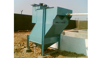
Introduction:-
Lamella name is derived from the LAMINAR FLOW regime that is maintained between
the two layers of the media.
Lamella Clarifier is used for settling of flocculated raw water in water treatment
plants. The system consists of no. of square tanks with inclined plates or tube
packs on the top portion. Lamella Clarifier is a compact, inclined plate type of
clarifier. It is used for clarification of water, waste water and liquid having
suspended and colloidal particles. Principle of Lamella Clarifier is based on settling
under gravity, providing number of inclined plates to give large projected surface
area.
Working Principle:-
The Lamella Clarifier provides a means of water clarification at a large saving
of plant surface area. The clarifier consists of a series of inclined overlapping
plates, which are arranged to form a separate sedimentation chamber or the cells
between each pair of adjacent plates. The overlapping additive projected area of
several plates is a factor of increased surface settling area proportioned to the
number of plates used.
Before entering to Lamella Clarifier, water is first fed to Flash Mixer and Flocculation
Tank (FMFT). Chemicals like alum, ferric chloride, lime are added in flash mixer
in which high-speed agitator is provided for proper mixing of chemicals in water.
Water from flash mixer enters in flocculation chamber in which paddle type agitator
is provided for gentle mixing. Polymer is added for flocculation of coagulated particles.
Sufficient residence time is provided in this chamber for particles to become heavy
before entering into Lamella Clarifier.
Static mixer can replace the flash mixer. In such case, chemicals were added prior
to static mixer. The zigzag vanes are provided in static mixer to do proper mixing
of chemicals.
The pretreated feed stream enters the Lamella and transverses through feed ducts
longitudinally, along each side of the Lamella plates, through a bottomless distribution
duct. The liquid/solid feed stream then enters each plate chamber near the bottom
section of the plates and flows upward between them. As the feed stream moves upwards,
solids settle downward by the plates descending a short distance onto the surface
area provided by the plates. Solids continue to slide down the plate surfaces to
a collection hopper.
Near the top of each plate, water leaves each cell through a pair of circular openings
in the adjustable weir plate located along each side of the clarifier. The weir
plate should be set horizontally and in level so as to provide proper distribution
of liquid through each circular opening. It should also be set at a height to provide
a design water level below top of the tank.Sludge is periodically removed by opening
the drain valve provided in the hopper bottom of the Lamella clarifier.
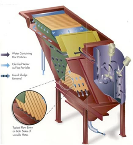
Features :-
Flow entry - The flow enters from both sides of
the plate. Distribution and entry velocities are minimum to optimise the hydraulic
flow regime, resulting in full plate utilisation, maximum efficiency and better
effluent quality.
Weir take-off - A weir launder provides an effective
weir length. The weir has orifices on either side of each plate.
Removable plates - Individual plates are easily
removable even during operation, making the unit very simple to maintain. The design
offers flexibility to handle changes in influent characteristics.
Hopper Arrangement - Several options are available
for sludge storage. The standard arrangement is a hopper bottom with a structural
support frame. A second option is to mount the lamella clarifier on top of a thickener
in order to achieve a higher solids concentration, while providing a large sludge
volume.
Applications:-
- Ash / Scrubber waste treatment
- Brine Clarification
- Clarification of water
- Coal and other mineral separation
- Filter backwash water recovery
- Food and dairy processing and wastewater
- Iron Removal
Advantages:-
- Sedimentation tank size smaller
- Plates prevent sludge carry over while sliding
Flocs snow ball
- Any time Start up, no operational delay
- High efficiency separation even at minimum density
of Floc
- Unaffected by Hydraulic shock loads
- With recycle dirty water, excellent performance
even in low turbidity.
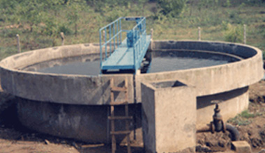
Clariflocculators
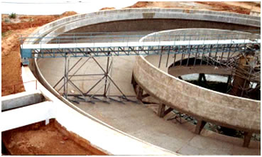
Basic Structure and process:-
Lichens's Clariflocculators unit is a combination of both
flocculation and clarification in a single tank. This unit consists of concentric
circular compartments. The inner compartment is the flocculation chamber and the
outer compartment is the clarifier. The chemically dosed water is uniformly distributed
over the surface of the flocculation compartment for effective utilization of the
available volume for flocculation. The specially designed flocculating paddles enhance
flocculation of the feed solids.
As heavy particles settle to the bottom, the liquid flows radically outward and
upward and the clarified liquid is discharged over a peripheral weir into the peripheral
launder. The deposited sludge is raked to the bottom near the central pocket from
which it can be easily discharged.
Both central driven and peripheral driven mechanisms are available in Lichens manufacturing
range
CENTRAL DRIVE CLARIFLOCCULATORS 3 MT. DIA TO 50 MT. DIA
This unit is suitable for installation in client’s concrete tank. Each unit
will consist of :-
- Fixed full bridge with walkway and handrail from
one end to center.
- Center drive with Motor, Gear box, Base plate,
V- Belts.
- Central heavy duty bearing housing.
- Central shaft.
- Clarifier rake arms with blades.
- Flocculator drive with motor and gear box.
- Flocculator shaft.
- Flocculator paddles.
- Flocculator chamber in steel.
SALIENT FEATURES OF “Lichens” CENTRAL DRIVE CLARIFLOCCULATOR
Unlike other Clariflocculators, having two separate drives, we offer a central paddle
flocculator, which has flocculating paddles Intermeshing with vertical paddles attached
with the scrapper arm. This provides a high degree of flocculation and hence is
more efficient.
PERIPHERALLY DRIVEN CLARIFLOCCULATORS 3 MT. DIA TO 50 MT. DIA
This unit is suitable for installation in client’s concrete tank. Each unit will
consist of :-
- Rotating half bridge with walkway and handrails.
- End Drive with motor, gear box, base plate, V-belts.
- Central bearing housing and slip ring assembly.
- Wheels rubberized C.I.
- Central cage.
- Clarifier rake arms with blades.
- Flocculator drive with motor, gear box.
- Flocculator paddles.
- Flocculator rake arms with blades.
- All pipes, including inlet, outlet and sludge
pipes are excluded from our scope
Applications:-
- Municipal water treatment plants
- Municipal wastewater treatment plants
- Industrial water and wastewater treatment plants
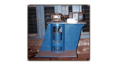
Oil Skimmer
Introduction:-
Oil skimmers or Oil removal systems are used in a waste water treatment plant to
remove excess oil from sewage or Industrial Effluent water.
MANUAL OIL SKIMMER:
This is suitable for installation in client’s concrete tank. Each unit will consist
of :-
- Slotted oil pipe in HDPE/M.S. Epoxy painted.
- Clamp.
- Handle.
- Special bushes.
AUTOMATIC OIL SEPARATOR suitable for client’s RCC Oil separator.
Each unit will consist of :-
- Traveling trolley with 4 wheels.
- Drive arrangement of motor, gear box, chains and
sprockets.
- Skimmer Bracket with rubber squeegees.
- Guide angles with support brackets.
AUTOMATIC OIL SEPARATOR suitable for client’s Existing vessel.
The unit will consist of :-
- Float in S. S.
- Motor.
- Gear box.
- Skimming blade.
SALIENT FEATURES OF “Lichens” AUTOMATIC OIL SKIMMER
AUTOMATIC OIL SKIMMER
Each unit will consist of :-
- Motor.
- Drive unit.
- Oil collecting Disc.
- Rubber scrappers.
- Oil Collection Chamber.
- Oil pump.
OPERATION:-
The RCC Tank will have oil baffle on the outlet side and outlet water launder. The
unit consist of Motor, Gear, Oil collecting Disc with rubber scrappers, Oil Collection
Chamber, and oil pump.
The disc slowly rotates and offer a large surface area for oil to collect on the
same and the scrappers subsequently scrap the oil into the collection chamber, from
where it is pumped out.
SALIENT FEATURES OF OIL SKIMMER
- Compact unit without a traveling bridge/trolley.
- High oil removal efficiency.
- Practically, no water comes out with oil, thereby
ensuring good oil recovery.
Bar Screen
Introduction:-
Bar screens are typically at the headworks (entrance) of a wastewater treatment
plant (WWTP), bar screens are used to remove large objects such as rags, plastics
bottles, bricks, solids, and toy action figures from the waste stream entering the
treatment plant.
MANUAL BAR SCREEN:
This structure is suitable for installation in client’s concrete screen chamber.
Each unit will consist of :-
- Screen frame consisting of flats.
- Handle.
AUTOMATIC SCREEN:
Each unit will consist of :-
- Drive arrangement consisting of Motor, Gear box
and bearing housing.
- Rake mechanism.
- Screen frame with screen bars.
Grit Collector
Introduction:-
These units are optimally designed for the required hydraulics to ensure optimum
grit separation even at peak hydraulic load.
GRIT REMOVAL MECHANISM:
This unit is suitable of installation in clients concrete tank. Each unit will consist
of :-
- Rotating bridge with drive arrangement of Motor,
Gear box,coupling etc.
- Heavy duty central bearing housing to take care
of undulations in coping.
- Current collector.
- Grit washer with pump.
- Flexible hose for grit removal.
- Interconnecting piping for grit, washer and pump.
GRIT REMOVAL MECHANISM suitable of installation in client’s concrete tank. Each
unit will consist of :-
- Main drive unit with Motor and Worm Gear box.
- Shaft.
- Scrapper arms with blades and scoops.
- Tie rods.
- Diffuser baffle.
- Classifier drive system with Motor and gear box.
- Scrapper blades at bottom.
Advantages:-:
- Rugged precision gear/bearing drive located entirely above the waterline
- Low energy consumption
- Simple and inexpensive maintenance requirements
- Custom retrofit mechanisms available for existing tanks